Category
Plumbing
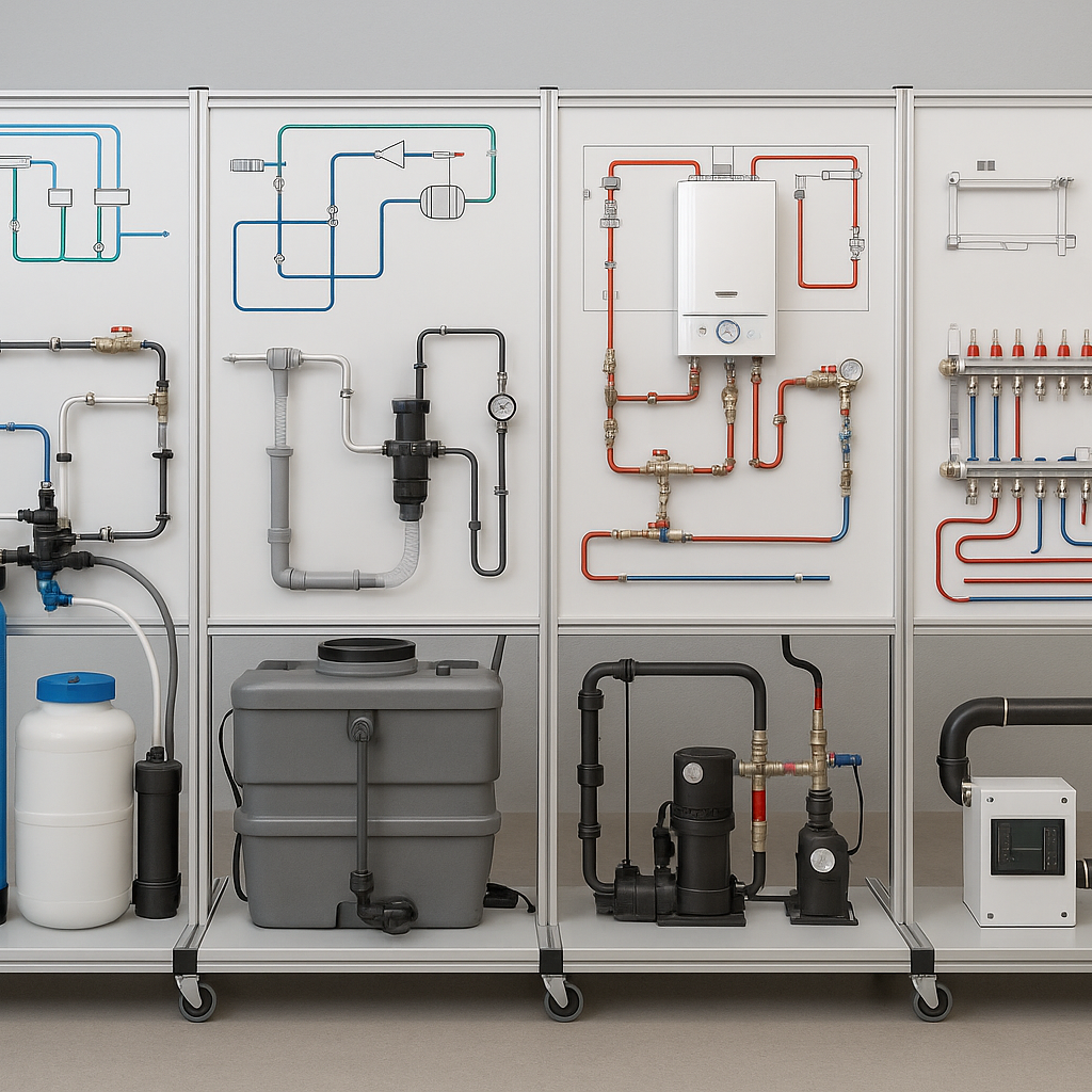
Plumbing Training Stand
TECHNICAL DOCUMENTATION
Drinking Water Treatment Stand
This educational stand demonstrates drinking water treatment technologies: mechanical filtration, iron removal, softening, and reverse osmosis. It enables learners to study the steps of water quality improvement and monitor relevant parameters.
Diagram / Scheme
Water inlet → Mechanical filter → Iron removal filter → Softener → Reverse osmosis system → Water storage tank → End user
Minimum Technical Parameters:
− Softener salt consumption: ~150 g/1 m³
Practical Exercises:
Wastewater and Rainwater Management Stand
This integrated stand is designed for learning about domestic wastewater treatment, rainwater harvesting, conservation, and filtration processes. It enables evaluation and application of modern wastewater management technologies.
Flow Diagram:
Indoor wastewater source → Conservation system → High-pressure flushing unit.
Outdoor rainwater system → Vacuum suction system → Storage tank.
Domestic recirculation system → Treatment unit → Discharge.
Minimum Technical Parameters:
Practical Exercises:
Heating System Maintenance Stand
This stand is intended for training in balancing, flushing, and venting heating systems. It enables students to perform practical tests for improving system performance.
Flow Diagram:
Boiler → Balancing unit → Flushing unit → Air venting station → Heating system network.
Minimum Technical Parameters:
− Air venting station operating pressure 2–6 bar.
Practical Exercises:
− Analyzing the effectiveness of flushing.
Underfloor Heating Automation Stand
This stand is designed for automatic control of underfloor heating systems and zone distribution. It allows training in temperature control and energy efficiency.
Flow Diagram:
Thermostatic controller → Zone distribution module → Underfloor heating loops.
Minimum Technical Parameters:
− System pressure: up to 4 bar.
Practical Exercises:
Pipe Diagnostics and Sanitary Fixtures Stand
This stand is designed for training in pipe diagnostics, fault detection, and energy loss analysis. It is suitable for plumbing and engineering education.
Flow Diagram:
Pipe inlet → Diagnostic camera → Fault detection system → Energy loss meter → Report generation system.
Minimum Technical Parameters:
− Energy loss analysis precision: up to 2%.
Practical Exercises: