TECHNICAL DOCUMENTATION
Drone assembly and testing training stand DRODRE1-1
GENERAL DESCRIPTION
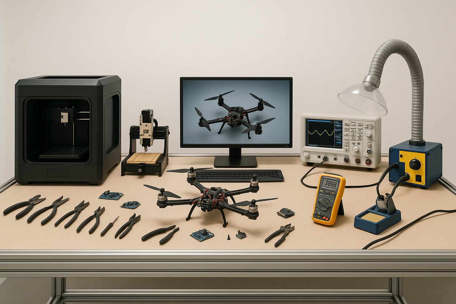
The drone assembly, testing, soldering, and component manufacturing training stand is an integrated complex designed for hands-on student training. The stand supports all key stages of drone development – from soldering components and printing parts to programming and flight testing. This solution is suited for modules within engineering, mechatronics, electronics, and aviation technical training programs.
Stand Components
Mechanical and Electronic Assembly
Soldering workstation with fixture tools.
2x soldering stations with adjustable temperature control.
Fume extractor fan with filters (ESD-safe).
Assembly tool kit: screwdrivers, pliers, tweezers, micro wrenches, ESD wrist straps.
Drawers and boxes for component storage.
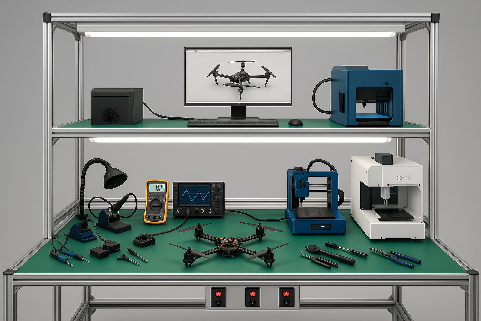
Testing Equipment
The test module is used for evaluating drone ESCs, motors, and batteries.
A digital multimeter with auto-ranging capability assists in accurate measurements.
The two-channel oscilloscope (100 MHz) provides signal analysis for electrical diagnostics.
A component tester supports the testing of IR sensors, MOSFETs, capacitors, and other parts.
The flight stability testing platform is used to assess drone balance and control.
A GPS verification station ensures accurate functionality of navigation modules.
Part Manufacturing and Modification
A 3D printer with 0.2–0.4 mm nozzle supports PLA and PETG filament use for prototyping.
A three-axis CNC milling machine enables precise cutting of aluminum and plastic parts.
A design computer with CAD/CAM software is provided for creating and adjusting parts.
Hand tools such as files, saws, and drills allow for manual adjustments and corrections.
Additional Equipment
Drone frame and electronics component kits are included to support complete build and testing workflows.
Charging stations for LiPo batteries ensure safe and efficient power management during training.
Safety goggles, gloves, and an ESD-safe mat are provided to maintain proper personal and equipment protection.
A projector or large display screen is available for delivering theoretical lessons and demonstrations.
An instruction board with QR codes is placed at each workstation to provide instant access to relevant guides and resources.
Description of stand modules by function
| Module | Purpose | Equipment |
| Soldering Area | Component soldering, wire connections | Soldering stations, fume extraction system, hand tools |
| Assembly Area | Drone frame and structure assembly | Assembly tools, screw storage system |
| Testing Area | Testing of electrical components and flight systems | Multimeter, oscilloscope, testing platform |
| Manufacturing Area | Design and production of parts | 3D printer, CNC milling machine, CAD workstation |
| Learning Area | Theoretical instruction and guidance | Projector, instruction boards |
Spatial organization (recommendation)
The stand occupies approximately 15–20 m² and is arranged in an L or U shape to ensure functional separation of work areas. Each zone is recommended to have 2–4 m² of space, depending on the number of students, allowing for efficient and safe workflow during practical activities.
Application areas and training modules
The stand is suitable for the following modules:
Soldering of electronic components.
Assembly and maintenance of UAV systems.
3D modeling and printing.
CNC milling.
Drone programming.
Testing analysis, safety, and battery maintenance.
Safety and certification aspects
All electrical components must be protected against overheating and ESD.
The soldering area must be equipped with a fume extraction system.
The 3D printer must operate within an enclosed chamber.
The battery charging area must include a fireproof containment unit.
Additional recommendations
Can be supplemented with programmable microcontrollers.
Integrate QR codes linked to video instructions.
Include AI or computer vision testing modules for advanced-level training.